Programmable Logic Controller (PLC)
Introduction to Programmable Logic Controller:
Programmable Logic Controller is an intelligent, rugged digital computer that executes the commands in real-time and is extensively used in the industries. PLCs are easy to program and have the ability to diagnose faults on its own. These devices could be in a compact and simpler form with few I/O ports (e.g., home automation) or could be complicated with hundreds of digital and analog I/O ports connected to several external devices , sensors, and actuators. These types of complex PLC are mainly used on the industrial level.
PLCs were first developed in the 1960s and were initially introduced in the automotive Industry. Initially, PLCs were unreliable and required uncompromising conditions to work. But, due to their unchallenging wiring, compact size, and simple troubleshooting mechanism, soon they gained a reputation in the market. With time and development, PLCs Made Drum Sequencers, Relays, and cam timers obsolete from the market.
Architecture of Programmable Logic Controller:
The architecture of PLCs is simple, contrary to its approach and utilization. PLCs include a processing unit that takes the input signal, then interprets it, and produces an output decision based on the program feed into it. Along with a CPU, PLCs have a power supply that converts AC Voltages into DC voltage. A memory unit is used to store the program and input data, which has to be executed by the processor. A communication module is used to transmit and receive data over the remote PLC console. PLCs require a programming device to scheme the operations and to update the system. Moreover, they need interfacing units for the reception of input-output signals.
Functionality:
The wide use of PLCs is due to its rugged compatible nature, even in severe situations such as heat, cold, moisture, and dust. Inputs of PLCs could be limit switches, analog inputs from different sensors (such as pressure and temperature sensors), or many complex data acquired by analyzing machine positioning or vision systems.
The primary function of PLCs is to operate distributed control systems, motion controls, sequential relay controls, process controls, and networking. Processing power, communication potential, and data handling of PLCs are highly efficient and unbeatable. PLCs can even outrun high-tech personal computers as their operating systems don’t allow them to accept logic execution with time consistency as compared to data executed by PLCs.
User Interface:
GUI is employed for the user interface purpose. It could also be referred to as HMI (Human Machine Interface) or MMI (Man Machine Interface). PLCs have buttons and lights over the panels to interact with the operator. Text Display Screen or Touch Screens are provided to display information. Moreover, Monitoring and Programming Systems are installed over PLCs to provide further assistance.
Working:
The PLC (Programmable Logic Controller) acts as a small scale computer that has the tendency to control machines and heavy-duty equipment.
The components of a standard PLC unit can be divided into three categories.
- The power supply and rack
- The central processing unit (CPU)
- The input and output section/Interface
The Power Supply and Rack of Programmable Logic Controller:
If we remove all equipment and all the parts attached to a PLC, we are left with only a simple structure/frame, i.e., rack and power supply, which provides a regulated DC power to other components.
The rack acts as the base for other components and ties everything together. The power is supplied to the PLC through a port in the rack. PLCs usually operate in the areas with AC supply, and PLCs operate on DC voltage. So, the power supply that comes along the PLC has an integrated system within that converts AC into DC.
The CPU:
The CPU is regarded as the brain of a computer, and this is where processing takes place. Inputs are analyzed and processed and then are converted into outputs. The PLC’s CPU is located in a section alongside the power supply port.
Depending on the PLC, CPU type can vary.
The CPU houses the following modules
- Microprocessor
- Memory chip
- Integrated circuits to control logic
- Monitoring and communications
The CPU runs on different modes:
- Programming Mode: In this mode, the CPU reads/processes the implemented logic
- Run Mode: In this mode, the logic is executed
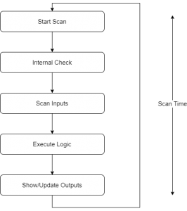
A PLC loops the process continuously, as long as it has power. When a PLC has successfully completed the execution one time that duration is termed as scan time. In the figure below, the Operating cycle is shown.
I/O System of Programmable Logic Controller:
As with every computer, the input devices can be digital or analog.
A digital input card deals with the digital devices which generate a signal of HIGH/LOW or ON/OFF. These devices include push-buttons, switches, flip switches, etc.
For the analog devices, an analog input card is responsible for the conversion of voltages or current into a digitally equivalent number for the CPU. For example, pressure plates and temperature readings use analog input cards to convey the readings to the CPU.
Similar to input devices, the output devices are also of two types digital and analog.
A digital output card sets the status of input as ON or OFF, e.g., the opening and closing of a door, switching on and off of street lights. An analog output card can convert a digital signal at the output to its actual values in terms of voltages or current. Usually, output signals range from 0 to 10 volts or 4 to 20mA.
Programming a PLC:
To begin programming on a PLC, usually ladder logic is used. Ladder logic was developed exclusively for programming a PLC. In ladder logic, symbols are used to program the device. These symbols are connected by a line that indicated the flow of the program. Just like other programming languages, ladder logic is sequential, and each new line in the program is called a rung.
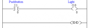
The name ladder logic is due to the appearance of the program, once it has been completed, as it resembles a ladder. The entire program is a representation of a circuit, and the rungs show the wiring and flow of current between the different modules.
Below is a fundamental ladder logic of a light source being controlled by a push-button.
Application
PLC’s find their applications in many industries, such as:
- Beverage production
- Food industries
- Automation industry
- Street/Traffic Lights
- Basically, any industry which aims to reduce human input to minimize errors uses PLCs
Vendors
Major Vendors of PLCs in Market include following
- Siemens
- Omron
- Insteon
- Keyence
- Panasonic
- Unitronics
- Alstom
- Echelon
end.
Read more PLC